Infiltration Galleries
Brief Description
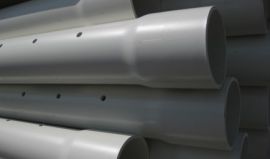
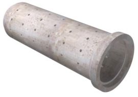
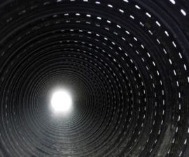
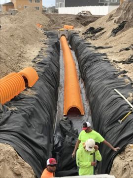
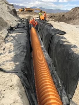
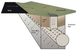
Typically, an infiltration gallery is a structure that is designed to dissipate stormwater through a pervious medium of straight graded rocks. These galleries can include dome structures that sit on a pervious layer of various thickness, through which the water penetrates the ground, and perforated pipes of various capacity depending on its design, surrounded by a pervious layer.
Cost Range
Construction: $$$
O&M: $
Ideal Conditions for Installation
Precipitation: Can be designed for high intensity and long duration
Soils: A and B, possibly C depending on the hydraulic transmission rate
Groundwater: Below the structure lowest part
Where/Applicability
Residential: Yes - away from structure foundations
Commercial: Yes - away from structure foundations
Ultra Urban: Limited
Industrial: Yes
Highway/Road: Yes - away from the road foundation system
Retrofit: Limited
Maintenance
Frequency: In dry climate it can be done yearly
Type: Visual inspection, remove accumulated fines and debris
Monitoring: Annual visual inspection
Permit Renewal: N/A
Performance
Total Suspended Solids (TSS) - Fine: Medium
Total Suspended Solids (TSS) - Coarse: High
Chloride: N/A
Total Nitrogen: N/A
Metals: Medium
Oils and Grease: Medium
Pathogens: High
- Disclaimers: The approximate removal efficiencies above are based on research and may differ from one location to another. TSS removal is a function of the particle size. Refer to manufacture for details.
Specifications
Pretreatment is recommended to remove sediments and floatables.
In general, follow manufacturer specifications.
Following is a possible special
Section Includes:
- Materials and procedures for installing the systems.
- Type, size, thickness designation.
Related Sections:
- Embankment, borrow and backfill - Excavation - Storm drain systems
References:
- AASHTO LFRD Section 12.12 - ASTM F2787, F2418, F2922
Notes:
1. Use coated deformed reinforcing steel bars conforming to AASHTO M 284 or M 111 and M 31 grade 60 respectively or GRFP bars according to the latest AASHTO standards.
2. Field cut and bend reinforcing steel to clear pipes and maintain 2" cover. Repair any damage or cuts to the epoxy coating on reinforcing bars.
3. Use concrete class 4000 psi (APWA 033004).
4. Use type ii or v cement (low alkali).
5. For type, number, location, and size of pipe and other structures see plans.
6. See plans for depression dimensions.
7. Provide 3/4" chamfer on all exposed concrete corners.
8. Provide pre-treatment unit from approved list.
9. Use only structures and pipe materials according to standards and as approved by the city.
Definitions:
Pipe and Pipe Arch are identified according to diameter or by span and rise, the following definitions, and according to corrosion class.
1. Cover - The vertical extent of soil above the crown of the pipe or culvert. Refer to DG Series Standard Drawings.
2. Cross Culvert - A transverse drain covered with embankment that allows surface runoff to pass under the embankment.
3. End Section - A structure commonly made of steel or concrete that is attached to one or both ends of a culvert or a pipe to retain the embankment, improve appearance, provide anchorage, improve discharge, and limit scour at the opening.
4. Headwall - A structure commonly made of concrete, placed at the end of culvert inlet or outlet or storm drain outlet, to anchor the pipe, to retain the highway embankment near the pipe end, and to protect the pipe ends from bank erosion and channel bed scour.
5. Invert - The floor, bottom, or lowest part of the internal cross section of a culvert, conduit, or storm drain.
6. Paved Invert - Lining of concrete, bituminous, or other materials placed in the invert to protect the invert from abrasion or to improve the culvert hydraulics.
7. Rise - The vertical height dimension of the box, pipe arch, and arch structure.
8. Skew - The angle between a line perpendicular to the roadway centerline and the longitudinal direction of the culvert barrel.
9. Soffit - The inside top or roof of a culvert, conduit, or storm-drain pipe.
10. Span - The horizontal dimension of a box culvert, pipe arch, or arch structure.
Submittals:
- Provide a manufacturer's Certificate of Compliance showing the product meets the referenced specifications.
- Furnish a Certification of Compliance from the manufacturer certifying coating thickness.
Materials:
- Filter fabric
Structure Types:
- Perforated Corrugated Aluminized pipes.
- Perforated Corrugated Metal Pipe.
- PVC Arch.
System Selection:
1. Use the same type and strength or thickness for the entire system.
2. Use the maximum height of cover to determine the strength or thickness of the system elements.
3. Perforated corrugated and smooth-lined high density polyethylene pipes (HDPE) - Use only HDPE Plastic Pipe up to 60-inch diameter that is certified by AASHTO National Transportation Product Evaluation Program (NTPEP) to meet AASHTO M 294 requirements and provide a copy of NTPEP certification to the Engineer.
4. Perforated corrugated and smooth-lined PVC pipes - Use up to 36 inch diameter.
5. Do not use precast, non-reinforced concrete pipe greater than 18 inch in diameter.
6. Do not allow pipes of different types of metal to contact each other. Use matching materials to make direct extensions of existing pipes.
7. Do not use pipe containing longitudinal lap seams if watertight pipe or watertight joints are required.
8. Do not use thermoplastic systems manufactured without UV inhibitors approved by the Materials Engineer in applications subject to direct sunlight.
Execution:
Domes:
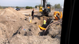
- Excavate the trench sufficiently wide, long and deep to place the pervious layer (stone matrix).
- At the proper elevation, place the filter fabric at the bottom of the trench, the fabric should be wide and long to envelop the pervious layer that is below the actual dome.
- Once the matrix is in place and is wrapped in fabric, the dome can be installed on the flatten matrix on the top of the fabric.
- Continue the operation for each segment of the system.
- Connect the dome system and structure to the inlet pipes per design.
- Backfill and compact in layers (8 inch to 12 inch) to 96% Mod. Proctor.
Perforated Pipes:
- Excavate the trench sufficiently wide, long and deep to place the pervious layer (stone matrix).
- Place outer filter fabric in the trench to keep the fines from migrating from the native into the pervious layer.
- Place the perforated pipes, connecting it.
- Follow manufacturer recommendations for the installation of filter and matrix envelope around the pipe for proper backfilling and complete installation of the system.
- Backfill and compact in layers (8 inch to 12 inch) to 96% Mod. Proctor.
Construction Sequence
The construction sequence varies according to the system chosen.
Domes:
- Design the system for the appropriate underlying soils infiltration rate, with a volume of retention according to storm frequency volume to be contained.
- Excavate the trench sufficiently wide, long and deep to place the pervious layer (stone matrix).
- Place outer filter fabric in the trench to keep the fines from migrating from the native into the pervious layer.
- Place outer filter fabric in the trench to keep the fines from migrating from the native into the pervious layer.
- Place layer of pervious material as per designed thickness and width.
- Place filter fabric that will wrap the pipe.
- Place the perforated pipes, connecting it.
- Follow manufacturer recommendations for the installation of filter and matrix envelope around the pipe for proper backfilling and complete installation of the system.
Perforated Pipes:
- Design the system for the appropriate underlying soils infiltration rate, with a volume of retention according to storm frequency volume to be contained.
- Excavate the trench sufficiently wide, long and deep to place the pervious layer (stone matrix).
- Place outer filter fabric in the trench to keep the fines from migrating from the native into the pervious layer.
- Place layer of pervious material as per designed thickness and width.
- Place filter fabric that will wrap the pipe.
- Place the perforated pipes, connecting it.
- Follow manufacturer recommendations for the installation of filter and matrix envelope around the pipe for proper backfilling and complete installation of the system.
Downloads
National Cooperative Highway Research Program Report
Generic Infiltration Galleries DWG
Links
Exfiltration Tanks/Trenches Reference
Design Standard
Cross-section