Outlet Skimmers or Shrouds (pre-treatment)


Brief Description
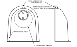
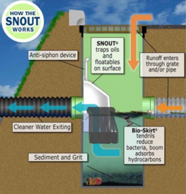
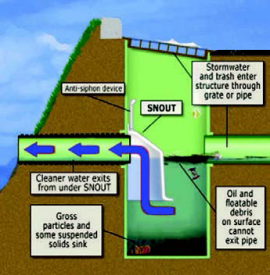
A skimmer or shroud is typically a hooded device (see drawing) that is installed over the outlet pipe in a storm drain structure with a deep sump that can help prevent floatables, sediments, and other trash debris from entering the outlet pipe.
Cost Range
Construction: $-$$
O&M: $$
Ideal Conditions for Installation
Precipitation: Lower Intensity, more frequent storms
Soils: N/A
Groundwater: Lower than the storm drain structure and inlet and outlet pipes
Where/Applicability
Residential: Yes
Commercial: Yes
Ultra Urban: Yes
Industrial: Yes
Highway/Road: Yes
Retrofit: Yes
Maintenance
Frequency: Monthly and after >0.5" storm events
Type: Sediment, oils, and trash
Monitoring: Inspect amounts of material collected
Permit Renewal: N/A
Performance
Total Suspended Solids (TSS): Low to medium
Chloride: N/A
Total Nitrogen (TN): N/A
Total Phosphorus (TP): N/A
Metals: Low
Oils and Grease: Low (can be high with addition filters of skirt)
Pathogens: Low
Floatable trash and debris: High
Feasibility: Any outlet structure
Specifications
Below are general specifications that may vary depending on the type, size, shape and manufacturer of snout and structure.
1. Snout materials may vary depending on manufacturer.
2. All hoods shall be equipped with watertight access port, a mounting flange, and an anti-siphon vent pipe and elbow as shown on manufacturer’s drawing.
3. The size and position of the hood shall be determined by outlet pipe size as per manufacturer’s recommendations (snout size shall be larger than pipe size).
4. The bottom of the hood shall extend downward a minimum distance equal to ½ the outlet pipe diameter with a minimum distance of 6” for pipes <12”I.D.
5. The anti-siphon vent shall extend above hood by minimum of 3” and a maximum of 12” according to structure configuration.
6. The surface of the structure where the hood is mounted shall be finished smooth and free of loose material and pipe shall be finished flush to wall.
7. All structure joints shall be watertight.
8. The hood shall be securely attached to structure wall with 3/8” stainless steel bolts and oil-resistant gasket as supplied by manufacturer. Install per manufacturer instructions.
9. Sump depth shall be 36” minimum for up to 12” ID pipe outlet. For pipes 15” ID and above, sump depth of 2.5 to 3 times pipe ID recommended.
Notes: 1. All hoods shall be constructed of a glass reinforced resin composite with ISO gel coat exterior finish with a minimum 0.125" laminate thickness.
2. All hoods shall be equipped with a watertight access port, a mounting flange, and an anti-siphon vent pipe and elbow as drawn. (See configuration detail)
3. The size and position of the hood shall be determined by outlet pipe size as per manufacturer's recommendation (snout size always larger than pipe size).
4. The bottom of the hood shall extend downward a minimum distance equal to 1/2 the outlet pipe diameter with a minimum distance of 6" for pipes <12" i.D.
5. The anti-siphon vent shall extend above hood by minimum of 3" and a maximum of 12" according to structure configuration.
6. The surface of the structure where the hood is mounted shall be finished smooth and free of loose material and pipe shall be finished flush to wall.
7. All structure joints shall be watertight.
8. The hood shall be securely attached to structure wall with 3/8" stainless steel bolts and oil-resistant gasket as supplied by manufacturer. (See installation detail)
9. Installation instructions shall be furnished with manufacturer supplied installation kit.
Execution
Installation kit shall include:
A. Installation instructions B. Pvc anti-siphon vent pipe and adapter C. Oil-resistant crushed cell foam gasket with psa backing D. 3/8" stainless steel bolts E. Anchor shields
Construction Sequence
Below are general installation instructions. Details may vary depending on the
type, size, shape of snout and structure including accessory installations.
1. Ensure storm drain structure is cleaned and prepared for snout installation.
2. Trial fit the snout over the outlet pipe to ensure proper sizing per specifications.
3. Drill hoes for anchor shields.
4. Place gasket on the snout flange and bolt snout to wall with manufacturers hardware.
5. Attach siphon and accessories (i.e. screens, skirts, deflectors) per
manufacturer's recommendations.
Downloads
Urban Drainage Design Manual
https://www.fhwa.dot.gov/engineering/hydraulics/pubs/10009/10009.pdf
Outlet Skimmers 1 DWG
https://d838380e-3ffd-4f23-b8ae-1169425c7f86.filesusr.com/ugd/4ec5f3_6981e2e28cc64c9dbe92581311d1389d.dwg?dn=09_ADP_StormwaterBMP_Outlet_Skimmers_1_2
Outlet Skimmers 2 DWG
https://d838380e-3ffd-4f23-b8ae-1169425c7f86.filesusr.com/ugd/4ec5f3_11a08008a6624e71938adbdd07a82821.dwg?dn=09_ADP_StormwaterBMP_Outlet_Skimmers_2_2
Links
Best Management Practices Reference
http://www.bmpinc.com/
USGS Catch Basin Reference
https://pubs.usgs.gov/sir/2010/5182/pdf/sir2010-5182_smith_catchbasin_508.pdf