Hydrodynamic Separators: Difference between revisions
Michaelfazio (talk | contribs) (Created page with "== Brief Description == == Cost Range == == Ideal Conditions for Installation == == Where/Applicability == == Maintenance == == Performance == == Specifications == =...") |
Ahmadsalah (talk | contribs) No edit summary |
||
| (One intermediate revision by one other user not shown) | |||
| Line 1: | Line 1: | ||
[[File:HydrodynamicSeparatorTrimmed.JPG|right|270px|Hydrodynamic Separator 1]] | |||
[[File:HydrodynamicSeparator2Trimmed.JPG|right|270px|Hydrodynamic Separator 2]] | |||
[[File:HydrodynamicSeparator3.png|right|270px|Hydrodynamic Separator 3]] | |||
== Brief Description == | == Brief Description == | ||
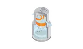
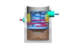
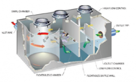
The Hydrodynamic Separator (HDS) is a Best Management Practice (BMP) that uses the energy of the stormwater and the shape of the structure to separate some pollutants from the water. The Hydrodynamic devices often enhance the rate of sediment settlement along with the capture of oil, grease, and other floatables. Hydrodynamic devices are typically designed to provide optimal removal efficiency for smaller, more frequent storms with minimal removal in larger, less common storms. | |||
== Cost Range == | == Cost Range == | ||
Construction: $$$ | |||
O&M: $$ | |||
== Ideal Conditions for Installation == | == Ideal Conditions for Installation == | ||
Precipitation: Smaller, more frequent storms | |||
Soils: N/A | |||
Groundwater: Depends on the manufacturer | |||
== Where/Applicability == | == Where/Applicability == | ||
Residential: Yes | |||
Commercial: Yes | |||
Ultra Urban: Yes | |||
Industrial: Yes | |||
Highway/Road: Yes | |||
Retrofit: Yes | |||
| |||
The system can be placed at the point source before the stormwater enters the storm drain system or before it outlets into a different system. | |||
== Maintenance == | == Maintenance == | ||
Frequency: Quarterly-Yearly | |||
Type: Sediment and floatable removal | |||
Monitoring: Review amount of sediment collected | |||
Permit Renewal: No | |||
== Performance == | == Performance == | ||
Total Suspended Solids (TSS): Medium | |||
Chloride: N/A | |||
Total Nitrogen: N/A | |||
Metals: Medium | |||
Oils and Grease: Medium | |||
Pathogens: Low | |||
== Specifications == | == Specifications == | ||
Pretreatment is recommended to remove sediments and floatables. | |||
1. The separator shall be sized to either achieve an 80 percent average annual reduction in the total suspended solid load or treat a flow rate designated by the jurisdiction in which the project is located. Both methods should be sized using a particle size distribution having a mean particle size (d50) of 125 microns unless otherwise stated. | |||
2. The separator shall be capable of capturing and retaining 100 percent of pollutants greater than or equal to 2.4 millimeters (mm) regardless of the pollutant’s specific gravity for flows up to the device’s rated-treatment capacity. | |||
3. The separator shall be designed to retain all previously captured pollutants addressed by this subsection under all flow conditions. The separator shall be capable of capturing and retaining total petroleum hydrocarbons. | |||
4. The separator shall be capable of achieving a removal efficiency of 92 and 78 percent when the device is operating at 25 and 50 percent of its rated-treatment capacity. These removal efficiencies shall be based on independent third-party research for influent oil concentrations representative of storm water runoff (20 ± 5 mg/L). | |||
5. The separator shall be greater than 99 percent effective in controlling dry-weather accidental oil spills. | |||
6. In order to not restrict the Owner’s ability to maintain the separator, the minimum dimension providing access from the ground surface to the sump chamber is recommended to be 16 inches in diameter. | |||
7. The separator shall be designed to capture and retain Total Petroleum Hydrocarbons generated by wet-weather flow and dry-weather gross spills. | |||
8. The separator shall convey the flow from the peak storm event of the drainage network, in accordance with required hydraulic upstream conditions as defined by the Engineer. | |||
9. The separator shall have completed field tested following TARP Tier II protocol requirements. | |||
== Construction Sequence == | == Construction Sequence == | ||
1. Typical systems, comprising of buried structures (manholes, vaults, etc.), are installed as part of the storm water treatment system. | |||
2. The connecting pipes entering and leaving the units normally require watertight connections. Follow manufacture recommendations for these connections. | |||
3. For any structures being installed, the loading capacity should be reviewed for placement in the roadway. The remaining fill material must be a Class I, II or III backfill and should be taken to at least 6" over the crown of the separator unit, but in no way less than the specified amount of cover per the manufacturer specifications or the engineer requirements. | |||
4. Reference the site plan to determine the location of the Separator Unit system. Determine the separator configuration, and compare it to the configuration specified on the detail Sheet. Determine if the unit is properly configured to accommodate the flow direction. | |||
5. Follow the installation instructions as provided by the supplier for connections, parts, etc. | |||
6. Excavate to proper depth, length, and width in accordance with regulations to ensure safe site conditions. | |||
7. Level subgrade to the proper elevation and check against finished grade and structure dimensions to ensure adequate depth. | |||
8. Generally the unit should be backfilled with Class I, II, or III material to the depth indicated above the crown of the unit, or as specified for traffic rated situations. | |||
9. Backfill to grade using Class I, II or III backfill or other suitable material. Compact the backfill according to geotechnical recommendations. | |||
== Downloads == | == Downloads == | ||
== Links == | == Links == | ||
CDS Stormwater Treatment Reference | |||
https://www.conteches.com/stormwater-management/treatment/cds | |||
Regulator Resources Reference | |||
https://baysaver.com/resources/regulator-resources/ | |||
Hydrodynamic Separators Reference | |||
https://www.stormwaterassociation.com/hydrodynamicseparators | |||
== Design Standard == | == Design Standard == | ||
Latest revision as of 14:25, 11 October 2021


Brief Description
The Hydrodynamic Separator (HDS) is a Best Management Practice (BMP) that uses the energy of the stormwater and the shape of the structure to separate some pollutants from the water. The Hydrodynamic devices often enhance the rate of sediment settlement along with the capture of oil, grease, and other floatables. Hydrodynamic devices are typically designed to provide optimal removal efficiency for smaller, more frequent storms with minimal removal in larger, less common storms.
Cost Range
Construction: $$$
O&M: $$
Ideal Conditions for Installation
Precipitation: Smaller, more frequent storms
Soils: N/A
Groundwater: Depends on the manufacturer
Where/Applicability
Residential: Yes
Commercial: Yes
Ultra Urban: Yes
Industrial: Yes
Highway/Road: Yes
Retrofit: Yes
The system can be placed at the point source before the stormwater enters the storm drain system or before it outlets into a different system.
Maintenance
Frequency: Quarterly-Yearly
Type: Sediment and floatable removal
Monitoring: Review amount of sediment collected
Permit Renewal: No
Performance
Total Suspended Solids (TSS): Medium
Chloride: N/A
Total Nitrogen: N/A
Metals: Medium
Oils and Grease: Medium
Pathogens: Low
Specifications
Pretreatment is recommended to remove sediments and floatables.
1. The separator shall be sized to either achieve an 80 percent average annual reduction in the total suspended solid load or treat a flow rate designated by the jurisdiction in which the project is located. Both methods should be sized using a particle size distribution having a mean particle size (d50) of 125 microns unless otherwise stated.
2. The separator shall be capable of capturing and retaining 100 percent of pollutants greater than or equal to 2.4 millimeters (mm) regardless of the pollutant’s specific gravity for flows up to the device’s rated-treatment capacity.
3. The separator shall be designed to retain all previously captured pollutants addressed by this subsection under all flow conditions. The separator shall be capable of capturing and retaining total petroleum hydrocarbons.
4. The separator shall be capable of achieving a removal efficiency of 92 and 78 percent when the device is operating at 25 and 50 percent of its rated-treatment capacity. These removal efficiencies shall be based on independent third-party research for influent oil concentrations representative of storm water runoff (20 ± 5 mg/L).
5. The separator shall be greater than 99 percent effective in controlling dry-weather accidental oil spills.
6. In order to not restrict the Owner’s ability to maintain the separator, the minimum dimension providing access from the ground surface to the sump chamber is recommended to be 16 inches in diameter.
7. The separator shall be designed to capture and retain Total Petroleum Hydrocarbons generated by wet-weather flow and dry-weather gross spills.
8. The separator shall convey the flow from the peak storm event of the drainage network, in accordance with required hydraulic upstream conditions as defined by the Engineer.
9. The separator shall have completed field tested following TARP Tier II protocol requirements.
Construction Sequence
1. Typical systems, comprising of buried structures (manholes, vaults, etc.), are installed as part of the storm water treatment system.
2. The connecting pipes entering and leaving the units normally require watertight connections. Follow manufacture recommendations for these connections.
3. For any structures being installed, the loading capacity should be reviewed for placement in the roadway. The remaining fill material must be a Class I, II or III backfill and should be taken to at least 6" over the crown of the separator unit, but in no way less than the specified amount of cover per the manufacturer specifications or the engineer requirements.
4. Reference the site plan to determine the location of the Separator Unit system. Determine the separator configuration, and compare it to the configuration specified on the detail Sheet. Determine if the unit is properly configured to accommodate the flow direction.
5. Follow the installation instructions as provided by the supplier for connections, parts, etc.
6. Excavate to proper depth, length, and width in accordance with regulations to ensure safe site conditions.
7. Level subgrade to the proper elevation and check against finished grade and structure dimensions to ensure adequate depth.
8. Generally the unit should be backfilled with Class I, II, or III material to the depth indicated above the crown of the unit, or as specified for traffic rated situations.
9. Backfill to grade using Class I, II or III backfill or other suitable material. Compact the backfill according to geotechnical recommendations.
Downloads
Links
CDS Stormwater Treatment Reference
https://www.conteches.com/stormwater-management/treatment/cds
Regulator Resources Reference
https://baysaver.com/resources/regulator-resources/
Hydrodynamic Separators Reference
https://www.stormwaterassociation.com/hydrodynamicseparators